Digisonde Antenna
Arrays
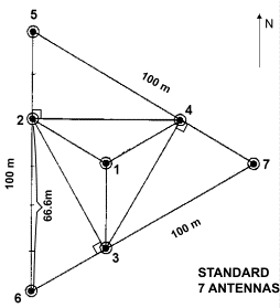
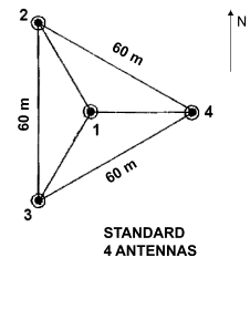
Two different types of antenna arrays can be implemented
in the Digisonde system. 7-antenna array is used for the
DGS256 (DISS) system while 4-antenna array is used with
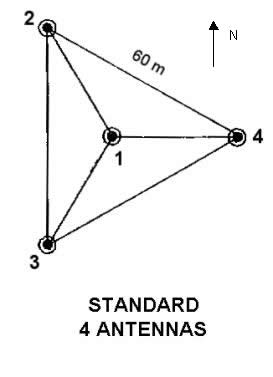
the DPS system. Figure 1 shows two types of standard-per-manual
antenna configurations.
|
 |
|
|
(a) |
(b) |
Figure 1. a) Standard Digisonde 7-antenna array configuration.
b) Standard Digisonde 4-antenna array configuration
Antenna
Array Specification for DDA
DDA Antenna configuration is specified
in the ddasetup.onl file, at the line *185 with the following
format:
*185
StationName <
LAT, LONG, CGPLAT, CGPLONG, COMPN, MAXSEP, DEVN, ROTATA
>
For example,
*185
HAARP
< 62.24, 214.91, 80.00, -80.00,
23.8, 103.92, -30.0, 13 >
Parameters LAT, LONG, CGPLAT, CGPLONG,
COMPN referring to the station location are explained
below.
LAT - Station Latitude
LONG - Station Longitude
CGPLAT - Corrected Geomagnetic Pole Latitude
CGPLONG - Corrected Geomagnetic
Pole Longitude
COMPNTD - Compass North Deviation
(a.k.a. Magnetic Declination Angle). Positive angles correspond
to the compass north deviation to the East of geographic
north.

Figure 2. Definition
of the COMPN parameter
Parameters MAXSEP, DEVN, ROTATA
specify the antenna configuration itself.
MAXSEP: This variable specifies the maximum antenna separation of the largest
triangle in the seven antenna array configuration (Figure
1a). Namely, MAXSEP is the distance in meters from antenna
5 to 6, 6 to 7, or 7 to 5. MAXSEP always refers to the outer antennas
of the seven-antenna system, even if they are not
present (as for
the 4-antenna setup of the DPS).
In the case of the DPS where only four antennas are
available, the MAXSEP is specified as the distance between
the virtual antennas 5, 6, and 7. For example, in the standard
DPS antenna layout, with 60 m long triangle side (distance
between antennas 2 and 3) MAXSEP should be set to103.92
m. In this case, the DPS antennas 2, 3, and 4 are referred
to as the inner antennas of the 7 antenna array.
DEVN:
Figure 3. Specification
of the DEVN parameter.
ROTATA. This parameter (a) defines
the antenna array configuration, and (b) also specifies
the output coordinate system for skymap and velocity data
calculated by the DDA software. Possible values for the
ROTATA parameter are defined in the following table.
| ROTATA |
Antenna
setup |
|
0 |
3 |
6 |
Clockwise rotating 7 antenna setup |
|
1 |
4 |
7 |
Clockwise rotating 4 Inner antenna
setup |
|
2 |
5 |
8 |
Clockwise rotating 4 Outer antenna
setup |
|
9 |
12 |
15 |
Counter-clockwise rotating 7 antenna
setup |
|
10 |
13 |
16 |
Counter-clockwise rotating 4 Inner
ant. setup |
|
11 |
14 |
17 |
Counter-clockwise rotating 4 Outer
ant. setup |
|
-1 |
-2 |
-3 |
Non-standard antenna setup |
|
Corrected
Geomagnetic |
Geomagnetic |
Geographic
|
|
|
Output
coordinate system |
Rotation Sense: This specifies the actual position of the antennas
in the triangular array.
In a seven‑antenna setup, antennas 6, 2, and
5 are located west of antenna 1, while antennas 4 and 7
are located east of antenna 1. This antenna field is said to be a counter-clockwise rotating field
since spiraling from antenna 2, 3, 4, 5, 6 to 7 the spiral
is in a counter-clockwise direction.
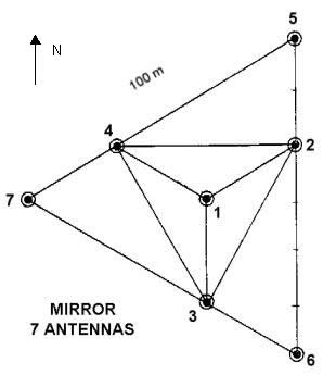
For the mirror image array where antennas 7 and 4
are located west of antenna 1 and antennas 6, 2, and 5 are
located east of antenna 1, the spiraling from antenna to
antenna goes in a clockwise direction.
Standard
Antenna Array Configurations
Historically,
three standard Digisonde antenna array configurations were
considered in the UMLCAR software for ionogram processing
(ADEP, Viewer, SAO Explorer):
·
Standard per manual
·
Mirrored (rotated 180° about
the X axis)
·
Rotated
(rotated 180° about the Z axis
Recently,
in support of our DIDBase (Digital Ionogram DataBase) development,
we have introduced a new scheme for specification of the
Digisonde antenna array configurations. The following antenna array nomenclature is now used:
·
Seven antennas standard
·
Seven antennas mirrored
·
Four antennas standard
·
Four antennas mirrored
DDA antenna specification examples for some
of commonly used antenna layouts can be found in the tables
below.
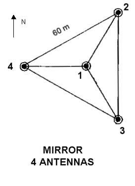
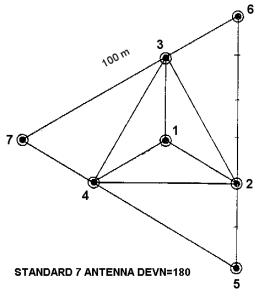
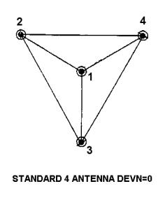
Four Standard Antenna Array Configurations
| Commonly
used in Digisonde 256 and DISS
DEVN = 0
MAXSEP = 100.0
ROTATA = { 9, 12, 15 } |

|
|
Known installations:
- Millstone
Hill
- Goose
Bay DISS
- Sondestrom?
DEVN = 0
MAXSEP = 100.0
ROTATA = { 0, 3, 6 } |
|
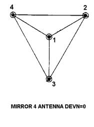
In the "standard"
configuration, antenna 1 to antenna 7 are walked counter-clockwise.
In the "mirror"
configuration, antenna 1 to antenna 7 are walked clockwise.
| Commonly used in DPS.
DEVN = -30
MAXSEP = 103.92
ROTATA = { 10, 13, 16 } |
|
|
Known installations:
DEVN = 30
MAXSEP = 103.92
ROTATA = { 1, 4, 7 } |
|
Other
known cases
Here's more examples of existing Digisonde antenna arrays configurations
in the new encoding scheme:
| Formerly "ROTATED DGS-256".
Known installations:
·
Karachi
·
Kokubunji
·
Beijing
DEVN = 180
MAXSEP = 100.0
ROTATA = { 9, 12, 15 } |
|
|
DPS working on the internal
loop of the array configuration "MIRRORED 7 ANTENNA
DEVN=0"
·
Millstone
Hill
DEVN = 0
MAXSEP = 103.92
ROTATA = { 1, 4, 7 } |
|
| DPS working on the internal
loop of the array configuration "STANDARD 7 ANTENNA
DEVN=0"
·
Sondestrom
·
Ramey
AFB
DEVN = 0
MAXSEP = 100.0
ROTATA = { 10,13, 16 } |
|
|
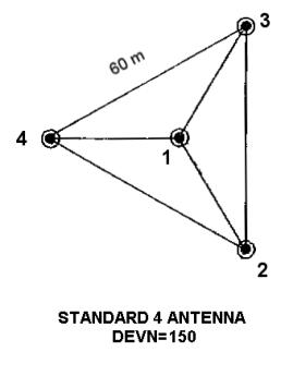
Formerly known as "DPS ROTATED"
·
Juliusruh?
DEVN = 150
MAXSEP = 103.92
ROTATA = { 10,13, 16 } |
|
Non-standard Antenna Array Configurations
If the antenna array configuration is not one of the standard (listed
above), such a non-standard setup is described by direct
specification of each antenna coordinates in the lines 170-183
of the ddasetup.onl file or lines 080-082 of the Station
UDD file.
The ROTATA parameter shall be set negative in this case:
ROTATA = -1
DDA output is in Corrected Geomagnetic coordinates
ROTATA = -2
DDA output is in Compass coordinates
ROTATA = -3
DDA output is in Geographic coordinates
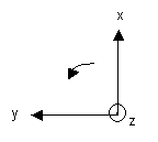
Individual antenna specifications
should made in the system of coordinates (Figure 4), where
·
X points to the Compass North at the time of installation
·
Z is the local vertical pointing up, and
·
Y
forms the right-hand system (i.e., points to the West).
Figure 4. Coordinate system used in DDA for antenna orientation
Note: For non-standard antenna configurations,
there is no need to specify parameters MAXSEP, COMPN, DEVN
in ddasetup.onl file.